
 EN
EN


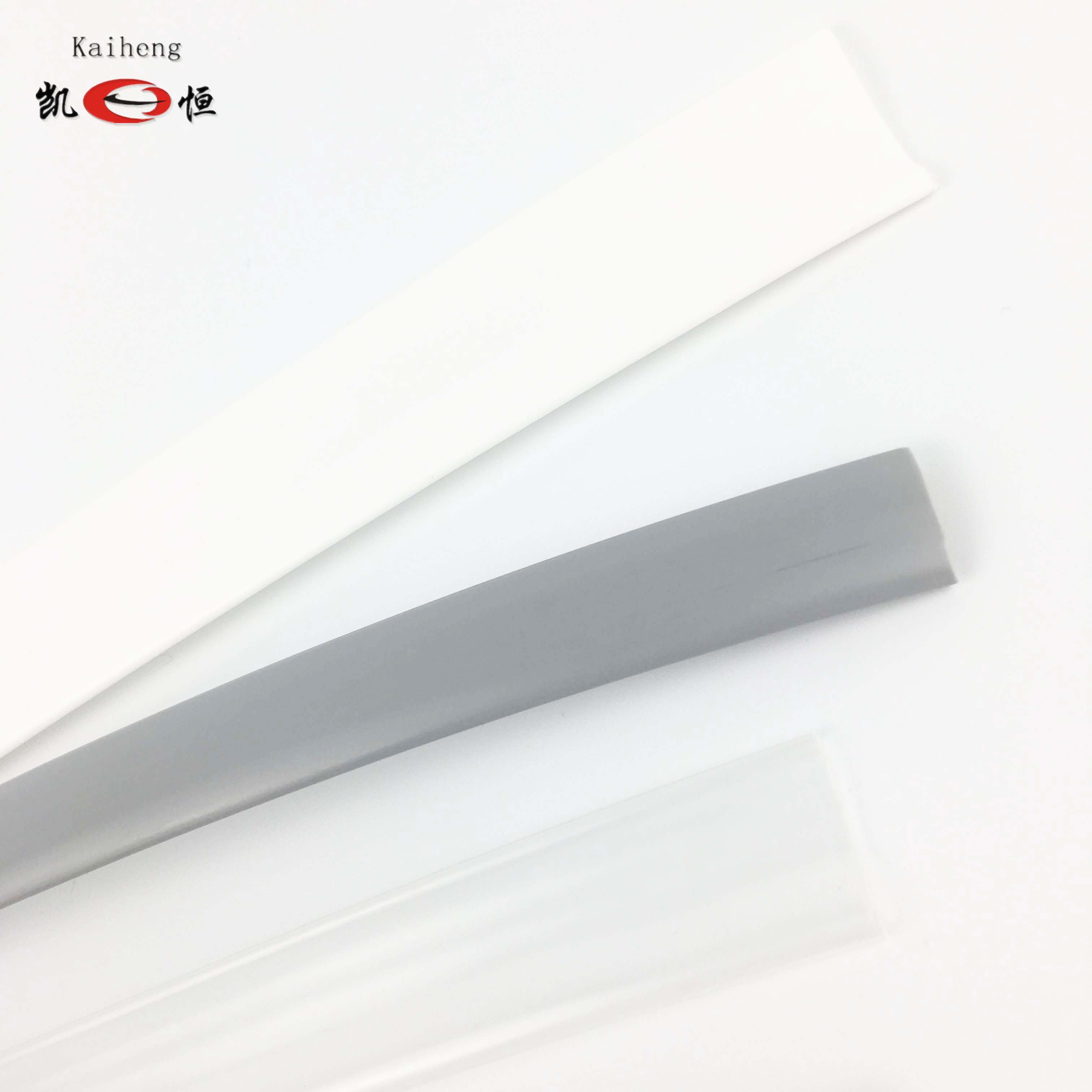
Telecommunications infrastructure is built on precision, reliability, and long-term performance. Every connection, junction, and wire bundle inside a telecom system must be protected against moisture, mechanical stress, electromagnetic interference, and temperature fluctuations. heat shrink tubing has become one of the most trusted solutions for achieving all of these objectives simultaneously. Its ability to conform tightly to irregular shapes while providing durable insulation makes it indispensable in modern telecom applications.
Understanding how heat shrink tubing is applied in telecommunications equipment requires a closer look at both the technical workflow and the specific environments where it performs best. From cable splicing in outdoor cabinets to protecting delicate fiber optic connections inside central offices, the application process follows defined steps that ensure consistent, professional results. This article walks through each stage of that process and explains why proper application matters so much in telecom environments.
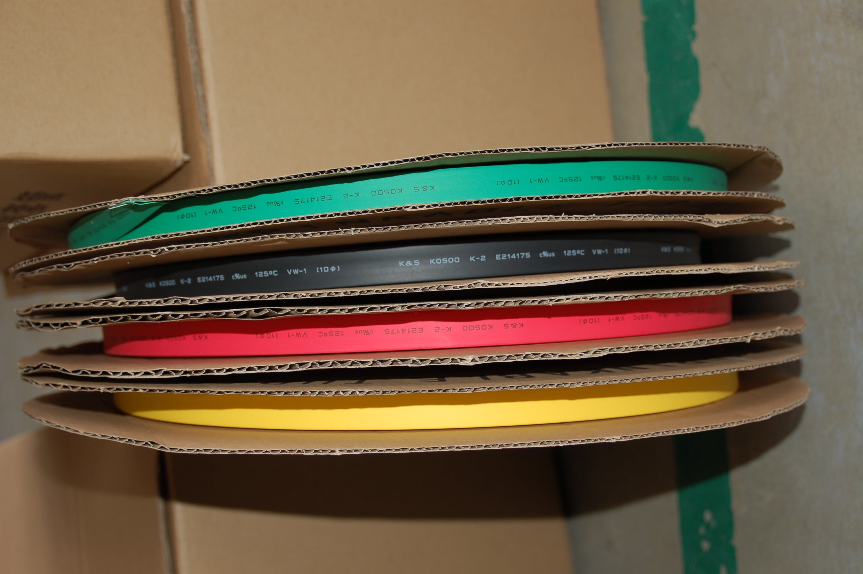
The Role of Heat Shrink Tubing in Telecommunications Infrastructure
Why Telecom Environments Demand Reliable Insulation
Telecommunications equipment operates across an enormous range of conditions. Outdoor base stations endure rain, UV exposure, and temperature swings from below freezing to intense summer heat. Indoor switching equipment faces humidity, dust, and vibration. In both environments, unprotected connections can fail quickly, leading to service interruptions that affect thousands of users.
Heat shrink tubing addresses these challenges by creating a sealed, insulating sleeve over any cable, connector, or splice point. Once applied with heat, the tubing shrinks uniformly to conform tightly to the underlying surface. This eliminates air gaps where moisture could collect and prevents the physical abrasion that gradually degrades bare wire insulation.
In telecom systems, even minor insulation failures can cause signal degradation, ground faults, or short circuits. Heat shrink tubing provides a simple, cost-effective layer of protection that extends the service life of expensive components and reduces maintenance costs significantly over time.
Common Telecom Applications Where Heat Shrink Tubing Is Used
Heat shrink tubing appears throughout the full lifecycle of a telecom installation. During initial construction, technicians use it to insulate wire terminations on patch panels, protect solder joints on antenna feed cables, and bundle control wiring inside equipment racks. Each of these tasks benefits from the tubing's ability to create a clean, professional finish without bulky mechanical fittings.
In the field, heat shrink tubing is widely used for cable entry sealing where multi-conductor cables pass through outdoor enclosure walls. A length of tubing slid over the cable and shrunk against the gland fitting creates a watertight seal that meets IP-rated protection standards. This application is particularly important in remote cell tower installations where regular maintenance is difficult and moisture ingress can be catastrophic.
Fiber optic technicians also rely on heat shrink tubing to protect fusion splice points. Specialized fiber splice protectors use a small length of heat shrink tubing over a stainless steel strength member to create a rigid, protected sleeve around the delicate glass splice. This is arguably the most precision-critical application of heat shrink tubing in the entire telecom industry.
Step-by-Step Application Process in Telecom Settings
Selecting the Correct Size and Material
Before heat shrink tubing can be applied, the correct size must be chosen based on the diameter of the substrate. The tubing's pre-shrink inner diameter must be large enough to slide freely over the connector or wire bundle, while the post-shrink diameter must be small enough to grip the surface firmly. Most heat shrink tubing products are rated with a 2:1 shrink ratio, though 3:1 and 4:1 options are available for irregular or large-diameter substrates common in power supply cabling within telecom systems.
Material selection is equally important. Standard polyolefin heat shrink tubing is the most common choice for general wiring protection in telecom equipment because it offers a good balance of flexibility, chemical resistance, and temperature rating. For applications involving harsh outdoor environments or exposure to fuels and oils near backup generator systems, adhesive-lined or cross-linked polyolefin variants provide enhanced sealing and chemical resistance.
Selecting the wrong size is one of the most common application errors. Tubing that is too large will not shrink down enough to grip securely, leaving gaps that allow moisture and contaminants to penetrate. Tubing that is too small cannot be positioned over the substrate before heat is applied, making the installation impossible without damaging the underlying component.
Preparing the Surface Before Application
Proper surface preparation is a step that is often overlooked but critically important for achieving a durable result with heat shrink tubing. The substrate must be clean, dry, and free of oils, flux residue, and loose particles before the tubing is positioned. In telecom environments, connector pins and wire terminations frequently have flux residue from soldering operations, which must be removed with an appropriate solvent before the tubing is applied.
Any sharp edges on connector bodies or wire cut ends should be smoothed before sliding the tubing into position. Sharp protrusions can pierce or weaken the tubing during or after shrinking, creating a point of vulnerability that defeats the purpose of the protection. A small amount of care at this stage prevents premature failure that could require complete rework later.
When working with adhesive-lined heat shrink tubing, surface preparation becomes even more critical because the hot-melt adhesive bonds directly to the substrate. Contaminants on the surface will prevent proper adhesion and create voids in the seal. This directly compromises the moisture exclusion performance that adhesive-lined tubing is specifically chosen to provide.
Positioning and Centering the Tubing
Once the correct length of heat shrink tubing has been cut, it must be positioned symmetrically over the area to be protected. For a wire splice, this means centering the tubing so that it extends at least 10 to 15 millimeters beyond each end of the splice. This overlap ensures that after shrinking, the tubing covers the full length of the joint and creates a smooth transition onto the adjacent wire insulation.
For fiber optic splice protectors, positioning is even more precise. The splice sleeve must be centered over the fusion point with equal overlap on each side of the bare fiber zone. Any offset will result in uneven protection and may expose the fragile glass splice to mechanical stress that could cause it to fracture under the bending loads present inside a fiber optic tray.
In high-volume telecom assembly environments, jigs and fixtures are often used to hold components in alignment while the heat shrink tubing is positioned. This ensures consistent placement across thousands of identical assemblies and reduces the risk of positioning errors that would require rework.
Applying Heat Evenly and Safely
The shrinking process is initiated by applying heat uniformly along the length of the tubing. A heat gun set to an appropriate temperature is the standard tool for professional telecom installations. The technician holds the heat gun about 25 to 50 millimeters from the tubing surface and moves it in a slow, sweeping motion from the center outward toward each end. This technique drives air out from beneath the tubing and produces a smooth, wrinkle-free result.
Temperature control is critical. Standard polyolefin heat shrink tubing typically begins shrinking at around 90 degrees Celsius and reaches full recovery at approximately 120 degrees Celsius. Applying excessive heat can cause the tubing to split, discolor, or bond unevenly, particularly at the edges. Insufficient heat leaves the tubing partially recovered, reducing its grip and sealing effectiveness.
In field conditions where a heat gun is not available, other heat sources such as a butane torch may be used, but with significantly more risk of overheating. Professional telecom technicians prefer calibrated heat guns because they provide consistent, controllable heat output that produces reliable results every time. The use of open flame near sensitive fiber optic and electronic components is generally avoided whenever possible.
Quality Assurance After Heat Shrink Tubing Application
Visual Inspection Criteria
After the heat shrink tubing has cooled, a visual inspection should confirm that the tubing has shrunk smoothly and evenly along its entire length. There should be no bubbles, wrinkles, or areas where the tubing has not made full contact with the substrate. The edges of the tubing should show a clean, gradual taper where the material transitions onto the adjacent wire or connector body.
For adhesive-lined heat shrink tubing, a small bead of adhesive should be visible at each end of the sleeve. This indicates that the hot-melt adhesive has flowed and filled all voids between the tubing and the substrate, creating the watertight seal the application requires. The absence of adhesive at the edges suggests the tubing was not heated sufficiently or was misaligned before shrinking.
Discoloration, cracking, or charring of the heat shrink tubing surface indicates overheating. While the tubing may appear to have shrunk correctly, overheating degrades the polymer structure and significantly reduces the long-term mechanical and electrical performance of the installation. Overheated sections should always be removed and replaced before the equipment is put into service.
Mechanical and Electrical Testing Protocols
Beyond visual inspection, professional telecom installations include mechanical pull testing of spliced connections to verify that the heat shrink tubing has not weakened the joint. The tubing itself adds some mechanical reinforcement, but the underlying connection must retain its specified pull strength. Any joint that fails under the specified test load must be reworked, regardless of how the heat shrink tubing appears visually.
Electrical continuity testing confirms that the conductors beneath the heat shrink tubing remain properly connected after the thermal process. Although properly applied heat shrink tubing should not affect electrical continuity, the heat can occasionally cause a marginal solder joint to fail if it was not properly formed during the initial assembly. Early detection of these failures through testing prevents expensive field failures later.
In fiber optic applications, an optical time domain reflectometer test is performed after splice protection sleeves are applied to verify that the optical insertion loss at the splice point has not increased due to mechanical stress introduced during the heat shrink application process. This is the definitive quality check for fiber splice protection work.
Factors That Influence Heat Shrink Tubing Performance in Telecom Equipment
Environmental Exposure and Material Compatibility
The long-term performance of heat shrink tubing in telecom applications depends heavily on matching the material to the operating environment. Standard polyolefin performs well in typical indoor equipment environments with operating temperatures up to 90 degrees Celsius. However, equipment installed in rooftop cabinets, outdoor enclosures, or near heat-generating power amplifiers may require tubing rated for continuous operation at higher temperatures.
UV resistance is another critical factor for any heat shrink tubing exposed to direct sunlight. Standard polyolefin formulations can become brittle and crack after extended UV exposure if they do not contain UV stabilizers. For all outdoor telecom installations, UV-resistant grades of heat shrink tubing should be specified to prevent premature degradation that could compromise the protection of underlying cable assemblies.
Chemical compatibility must also be considered in environments where cable jackets, cleaning agents, or lubricants used in installation may contact the tubing. Incompatible chemicals can cause swelling, softening, or premature cracking that defeats the insulation function of the heat shrink tubing. Material data sheets for the specific tubing grade being used should always be consulted before deployment in chemically challenging environments.
Shrink Ratio and Wall Thickness Considerations
The shrink ratio of heat shrink tubing determines how much size reduction occurs between the pre-shrink and post-shrink states. A 2:1 ratio means the tubing shrinks to half its original diameter. This is sufficient for most standard telecom cable diameters, but when working with connectors that have significant shoulder profiles or when bridging between a large connector body and a much smaller wire, a 3:1 or 4:1 ratio product provides a better fit without requiring multiple layers.
Wall thickness affects both the mechanical protection level and the flexibility of the finished assembly. Thicker-walled heat shrink tubing provides better resistance to abrasion and cutting forces, which is valuable in environments where cables pass through cable trays or conduits with sharp edges. However, thicker walls also reduce flexibility, which can be a disadvantage in applications requiring tight bend radii, such as cable routing inside densely packed equipment racks.
Telecom engineers and procurement specialists should evaluate both the shrink ratio and wall thickness together when specifying heat shrink tubing for a particular application. Choosing a product with the correct combination of these two parameters ensures that the installed protection meets both the mechanical and dimensional requirements of the design without compromising the flexibility and serviceability of the finished assembly.
FAQ
What is the most important factor when selecting heat shrink tubing for outdoor telecom applications?
UV resistance and moisture sealing capability are the most important factors. For outdoor use, adhesive-lined heat shrink tubing with UV stabilizers in the polymer formulation provides the best long-term performance. The adhesive liner creates a watertight seal that prevents moisture ingress, while the UV-resistant outer layer prevents the tubing from becoming brittle and cracking under prolonged sunlight exposure.
Can heat shrink tubing be removed and replaced if a telecom connection needs to be repaired?
Yes, heat shrink tubing can be removed by carefully slitting it lengthwise with a sharp blade or a specialized tube cutter, taking care not to damage the underlying cable or connector. After completing the repair, a new length of heat shrink tubing is slid over the reworked connection and shrunk in place following the standard application process. It is important to use the same size and material grade as the original installation to maintain consistent protection standards.
How does heat shrink tubing differ from electrical tape in telecom cable protection?
Heat shrink tubing provides significantly more durable and reliable protection than electrical tape in most telecom applications. Electrical tape can unwind, lose adhesion at high temperatures, and absorb moisture over time. Heat shrink tubing forms a permanent sleeve that maintains its shape, does not unravel, and provides consistent insulation resistance throughout its service life. For permanent installations in telecommunications infrastructure, heat shrink tubing is the professional standard.
What shrink temperature should be used when applying heat shrink tubing near sensitive electronic components in telecom equipment?
Standard polyolefin heat shrink tubing requires temperatures between 90 and 120 degrees Celsius for full recovery. When working near temperature-sensitive components such as capacitors, plastic connector housings, or optical fiber, a low-shrink-temperature formulation rated to recover at 70 to 90 degrees Celsius should be used. A calibrated heat gun with a focused nozzle attachment also helps direct heat precisely onto the tubing while minimizing thermal exposure to adjacent sensitive components.
Table of Contents
- The Role of Heat Shrink Tubing in Telecommunications Infrastructure
- Step-by-Step Application Process in Telecom Settings
- Quality Assurance After Heat Shrink Tubing Application
- Factors That Influence Heat Shrink Tubing Performance in Telecom Equipment
-
FAQ
- What is the most important factor when selecting heat shrink tubing for outdoor telecom applications?
- Can heat shrink tubing be removed and replaced if a telecom connection needs to be repaired?
- How does heat shrink tubing differ from electrical tape in telecom cable protection?
- What shrink temperature should be used when applying heat shrink tubing near sensitive electronic components in telecom equipment?